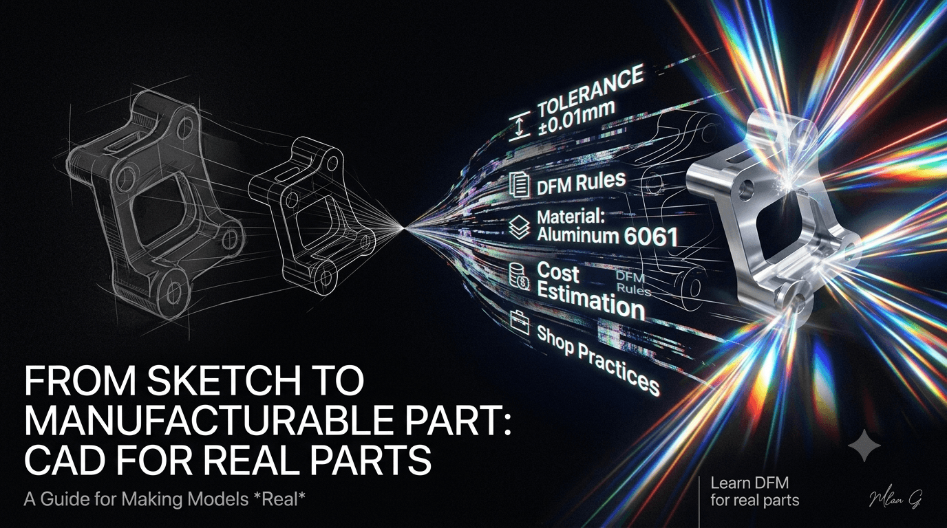
From Sketch to Manufacturable Part: CAD for Real Parts
A model that looks perfect can still be impossible to make. Learn how to turn a CAD model into a part a shop can actually produce, at a sensible cost and tolerance.
On this page
From Sketch to Manufacturable Part
Turning a CAD model into something a shop can actually make
What does manufacturable mean?
A model is manufacturable when a real process can produce it at a sensible cost and hold the tolerances the part needs.
That last part matters. A model can look perfect on screen and still be impossible to make, or possible but wildly expensive. A pocket with sharp internal corners cannot be cut by a round tool. A wall that is too thin will warp in a mold. A tolerance that is tighter than the machine can hold will get rejected or cost a fortune. Manufacturable means the shop can take your file and make the part without calling you to ask what you were thinking.
If you have read our CAD Fundamentals guide, you know how to build a clean model. This is the next step: making that model real.
Why the gap exists
Beginners design in a vacuum. The software lets you draw almost any shape, so it is easy to assume any shape can be built. Real processes have rules that the screen never shows you.
- Tools have a radius. A milling cutter cannot produce a perfectly sharp inside corner.
- Materials have limits. Thin walls warp, deep pockets chatter, tall thin features break.
- Every process has a grain. Machining, molding, sheet metal, and printing each make some shapes cheaply and others painfully.
The fix is to design with the process in mind from the start, not to finish a model and hope the shop can figure it out.
Design for the process
Once you know how a part will be made, you design its features to suit that method. Here are the habits that matter most for the common processes.
- Machining. Add a radius to internal corners so a round tool can reach them. Use standard drill sizes for holes. Avoid very deep, narrow pockets and very thin walls.
- Sheet metal. Keep one uniform thickness. Give every bend a radius, and add relief cuts where bends meet so the metal does not tear.
- Injection molding. Keep walls uniform, add a draft angle so the part releases from the mold, and use ribs instead of thick solid sections.
- 3D printing. Mind overhangs that need support, and orient the part so its strongest direction carries the load.
The single most common beginner fix is that internal fillet. A sharp inside corner is free to draw and impossible to machine. Adding a radius that matches a real tool turns an unmakeable feature into a routine one.
💡 Rule of thumb: before you add a feature, picture the tool or process that has to create it. If you cannot picture it, the shop cannot make it.
Tolerances belong only where they matter
A tolerance is how much a dimension is allowed to vary. Tighter tolerances cost more, every time, because they demand slower machining, better tooling, and more inspection.
So you spend tolerance like money. Tighten it only on features that must fit or mate with something else, such as a bore that holds a bearing. Leave everything else loose. A drawing with a tight tolerance on every dimension tells the shop you do not know which ones matter, and the quote comes back high.
You also need a drawing, even with a 3D model, because the drawing is where tolerances, datums, surface finish, and material are stated. The model shows the shape. The drawing states the rules the shape must obey.
A quick worked example
Take the L-bracket from the CAD guide and make it shop-ready.
- Add fillets to the internal corners that match a standard tool radius.
- Change the holes to a standard drill size so no special tooling is needed.
- Tolerance only the bore that locates a pin. Leave the outer dimensions at a general tolerance.
- Pick a material and process. Aluminium, milled from plate.
- Make a drawing stating the bore tolerance, the datums, the material, and the finish.
Same shape as before, but now it is a part a shop can quote and cut without a single question.
Common beginner mistakes
- Designing shapes a tool can never reach
- Putting a tight tolerance on every dimension
- Ignoring standard hole and material sizes
- Handing over a model with no drawing and no datums
- Never asking what the part will cost to make
Interview questions
These come up in design interviews because they show whether you think past the screen. Here is what the interviewer is listening for.
"How would you make this part cheaper to manufacture?" Talk about loosening non-critical tolerances, using standard sizes, reducing setups, and picking a process that suits the shape. Cost awareness is the signal.
"Why add a fillet to an internal corner?" Because a round cutting tool cannot produce a sharp internal corner. The fillet matches the tool radius and makes the feature machinable.
"We have a 3D model, so why do we still need a drawing?" Because the drawing carries the information the model does not: tolerances, datums, surface finish, and material. It states the rules, not just the shape.
"How do you decide which tolerances to tighten?" Tighten only features that mate or must fit precisely. Everything else stays at a general tolerance to keep cost down.
Quick reference
| Process | Design for it by | Watch out for |
|---|---|---|
| Machining | Fillet internal corners, standard holes | Sharp corners, deep narrow pockets |
| Sheet metal | Uniform thickness, bend radii, reliefs | Torn bends, mixed thicknesses |
| Injection molding | Draft, uniform walls, ribs | Thick sections, no draft |
| 3D printing | Mind overhangs and orientation | Unsupported overhangs, weak layer direction |
Key takeaways
If you remember five things, make it these.
- Manufacturable means a real process can make it, affordably, to the needed tolerance. A model that ignores this has not finished its job.
- Design with the process in mind from the start. Picture the tool that has to create each feature.
- Fillet internal corners so a round tool can reach them.
- Spend tolerance like money. Tighten only mating and critical features, and leave the rest loose.
- Always produce a drawing. The model shows the shape, the drawing states the rules.
Practice on FixtureLabs
Knowing the rules is one thing. Spotting the problem in a real model is another. On FixtureLabs, work through parts that force you to catch unmachinable features, place sensible tolerances, and choose the right process before a part reaches the shop.
Written by
FixtureLabs Inc.
FixtureLabs Inc. writes about fixture design, GD&T and how modern teams pair classical mechanical engineering with AI.