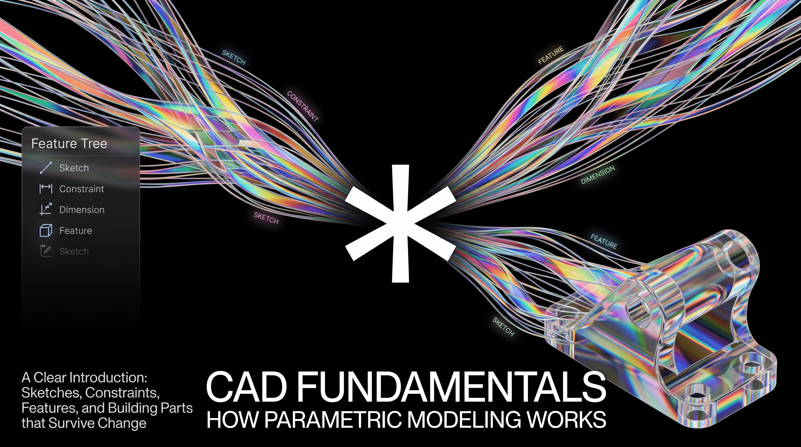
CAD Fundamentals: How Parametric Modeling Works
A clear introduction to CAD and parametric modeling. Learn what sketches, constraints, features, and the feature tree really are, and how to build parts that survive change.
On this page
- How parametric modeling actually works, and how to think like the software
- What is CAD?
- The one idea that matters
- Sketches and constraints
- Features: turning 2D into 3D
- The feature tree
- Design intent: the skill that matters most
- A quick worked example
- Manufacturing considerations
- Common beginner mistakes
- Interview questions
- Quick reference
- Key takeaways
- Practice on FixtureLabs
CAD Fundamentals
How parametric modeling actually works, and how to think like the software
What is CAD?
CAD stands for Computer-Aided Design. It is the software that engineers use to create the precise 3D models and 2D drawings that define a product before it is ever built.
Almost every manufactured object started as a CAD model. The phone in your hand, the chair you're sitting on, the car parked outside. Engineers use CAD to work out the exact shape and size of every part, check how those parts fit together, and hand a manufacturer a complete definition of what to make.
Modern CAD is far more than digital drawing. The model is intelligent. It understands dimensions and the relationships between parts. That intelligence is what makes CAD powerful.
The one idea that matters
Most people learn CAD as a drawing tool. It's actually a rule-building tool.
You're not drawing a picture of a part. You're teaching the software the logic of how the part is defined, so it can rebuild the geometry whenever something changes.
Everything below builds on that.
Sketches and constraints
Every 3D part starts as a 2D sketch on a flat plane.
A sketch isn't just a shape. It carries constraints, the rules that hold it in place. There are two kinds.
- Geometric constraints set relationships. A line is horizontal, two circles are equal, a point sits on an edge.
- Dimensional constraints set numbers. An edge is 50 mm, an angle is 30 degrees.
Add enough constraints and the sketch becomes fully defined. Every point is now pinned down, so the geometry can only ever be what you specified. That is the goal. An under-defined sketch is the number one reason models break, because any freedom left in it lets the geometry shift the moment you edit nearby.
💡 Rule of thumb: if a sketch looks right but isn't fully defined, it isn't done.
Features: turning 2D into 3D
A feature is a 3D operation. Four of them build the vast majority of parts.
- Extrude pushes a profile in a straight line
- Revolve spins a profile around an axis
- Sweep drags a profile along a path
- Loft blends between two profiles
The pattern is the same every time. A 2D profile plus one instruction for how to move it through space.
Real examples: a pressure vessel is a revolve, a bike frame tube is a sweep, a turbine blade is a loft, and most brackets and housings are extrudes.
The feature tree
You don't build a part in one move. You stack features in order, sketch then extrude then hole then fillet, and the software remembers the recipe. That ordered list is the feature tree, and it's the most important thing to understand in CAD.
The tree is the part's memory. From it you can:
- Double-click any feature to edit it
- Roll back to any earlier step
- Reorder operations
Learning to read and manage the tree is what separates someone who can make a model from someone who can maintain one.
Two habits pay off immediately.
- Name your features. "BasePlate, MountingBoss, WireSlot" beats "Extrude1, Extrude2, Cut1."
- Put fillets last. They depend on edges made by earlier features, so they're the most fragile. Keep them at the bottom of the tree.
Design intent: the skill that matters most
Here's the difference between an engineer whose parts update in ten seconds and one whose parts take a week.
Say you have a plate with four corner holes. Your boss says "make it wider." What happens to the holes?
If you dimensioned each hole from its nearest edge, all four ride outward and stay put in the corners. That edit takes ten seconds. If you hard-coded their positions from the origin, the model still rebuilds, but the holes on the right get stranded in the middle and the design is now wrong.
That's design intent. Capturing not just where geometry is, but why it's there and how it should respond to change. It's invisible in a finished model. You only see it when the model is edited. Build models that edit gracefully.
🤔 Design decision: a hole must always stay centered on a face as it resizes. Don't dimension it with X and Y numbers. Constrain it symmetric to the face's midplanes instead. Now it stays centered forever, with nothing to update.
A quick worked example
Model an L-bracket: 120 mm long, 95 tall, 20 deep, four Ø8 holes, R3 on the inside corner.
- Sketch the L-profile and constrain it fully.
- Extrude 20 mm.
- Add the holes at Ø8, dimensioned 15 mm from each nearest edge.
- Fillet the inside corner at R3, which reduces stress rather than just looking nice.
Four features, done. Now when the width changes, the edge-referenced holes update correctly on their own. That's the whole payoff of modeling with intent.
Manufacturing considerations
The model has to become a real object, so build the manufacturing method into it.
- Injection-molded parts need draft angles and uniform walls.
- Machined parts should avoid internal sharp corners a round tool can't reach.
- Fillets and chamfers often carry real meaning. An inside fillet may just be the cutting tool's radius, and a hole chamfer helps a bolt start.
A clean, well-named tree also means a manufacturing engineer can add a draft angle or split a face in five minutes instead of rebuilding your file.
Common beginner mistakes
- Leaving sketches under-defined
- Dimensioning everything from the origin, which kills design intent
- Cramming the whole part into one giant sketch
- Adding fillets too early
- Ignoring the feature tree
Interview questions
These come up constantly in mechanical design interviews, because they reveal fast whether someone understands CAD or just operates it. For each one, here's what the interviewer is really listening for.
"Walk me through how you'd model a simple bracket." They want a logical sequence of features and fully defined sketches, not a list of menu names. Talk through your plan before you touch the mouse.
"What does fully defined mean, and why do you care?" Say that a fully defined sketch has no remaining freedom, so geometry can't drift when the part is edited. Tie it to reliability, not tidiness.
"How do you decide where to place your dimensions?" The strongest answer is about design intent. You dimension from whatever a feature should stay attached to as the part changes, not from whatever is convenient.
"Your model failed to rebuild after an edit. How do you debug it?" Read the feature tree from the top. The first error is usually the real cause, and everything below it is just a knock-on effect. Fix the top one first.
"When would you choose an extrude over a revolve?" Extrude suits a part with a constant cross-section along a straight length. Revolve suits anything symmetric about an axis, like a shaft or a bottle. Naming a real part for each shows you think in shapes, not buttons.
Quick reference
| Concept | What it is | Why it matters |
|---|---|---|
| Sketch | A 2D profile on a plane | Raw material for every feature |
| Geometric constraint | A relationship such as horizontal or equal | Locks how geometry relates |
| Dimensional constraint | A number such as a length or angle | Locks how big it is |
| Fully defined | Every point pinned down | Geometry can't drift on edits |
| Feature | A 3D operation | Turns sketches into solid |
| Feature tree | The ordered recipe of features | The model's memory |
| Design intent | Capturing why geometry exists | Decides if a model edits well |
| Mate | An assembly relationship | Removes freedom between parts |
Key takeaways
If you remember five things, make it these.
- CAD is a rule-building tool, not a drawing tool. You describe geometry with constraints, and the software re-solves them whenever anything changes.
- Fully define every sketch. Any freedom left in a sketch is where models break, so pin every point down.
- Almost every part is an extrude, revolve, sweep, or loft. Train your eye to see which one a shape wants before you start.
- The feature tree is the part's memory. Keep it ordered, name your features, and put fillets last.
- Design intent is the highest-leverage skill in CAD. Dimension from whatever a feature should stay attached to, so the model updates the way you meant it to.
Practice on FixtureLabs
Reading builds intuition. Doing builds skill. On FixtureLabs, work through real modeling challenges that force these exact habits: fully defining sketches, choosing the right feature, and building parts that survive change. Start with the CAD track today.
Written by
FixtureLabs Inc.
FixtureLabs Inc. writes about fixture design, GD&T and how modern teams pair classical mechanical engineering with AI.